|
About classical electrodynamics
The
109 Experiment
The dramatic events of the last two
weeks call for a discussion of the historical progression to the
present.
In Ferranti in 1960, the
late Gordon Scarrott suggested that the interference
between logic signals travelling from the main computer to an additional
memory box (about the size of a piano) containing three thousand more (40
bit) words of memory might be caused by mutual inductance. Previous to his
remark, the consensus was that digital signals interfered with each other
by mutual capacitance – capacitive coupling. Previous computers used thermionic valves, with high voltages and low currents.
Our computer, “Sirius”, was the first transistorised computer, using low
voltages and heavy currents, making mutual inductance more significant.
While in Dataproducts Corp. in Los Angeles in 1964, Art Cappon came to the company to promote integrated
circuits manufactured by his company Motorola in Phoenix, Arizona. After a
conversation he decided that Motorola needed to get me to investigate
interference in digital systems. Motorola made the fastest (ECL 1nsec)
logic on the market. I was offered a job and refused. However, when Data
Products fired me two months later, I told Motorola that I had changed my
mind, sold my Los Angeles house, and took my family to Phoenix.
Motorola Phoenix were expert in semiconductors electronics and integrated
circuits, but lacked expertise in the field of electromagnetism, which is
where I came in. On a printed circuit board, a signal travelled six inches
in a nanosecond, so perhaps a major problem was to arise soon with their
1.35 nsec logic gates.
IBM was making a major
computer for NSA (National Security Agency), part of the Pentagon. This
contained a small high speed memory, the “Ballman
Scratchpad Memory”, at the centre of a hierarchy of memories. This memory
was to be 64 words, 8 bits per word, with an access time of 20 nsec and a cycle time of 20 nsec.
IBM said they could only achieve 35 nsec, so the
decision was made to subcontract the task of a nine month project to a
specialist Integrated Circuit company, Texas Instruments, to make a
partially populated model. However, there were complaints that TI always
got such contracts, so it was decided to give a split contract to TI and
Motorola.
At the time, 1964, an
integrated circuit package 1cm square contained only two memory bits. With
a delay of 1 nsec every six inches, the whole memory
had to be compressed into a cube less than one foot cube. The daughter
boards plugged into a mother printed circuit board which has thirteen
layers of copper, alternate signal wires and voltage planes. Manufacturing
such a board was expensive, and it was imperative that we knew in advance what was the interference between two parallel
signal lines in one of the middle planes.
I read the literature,
particularly Jarvis, reference
11 in my 1967 paper , and found that the interference depended on
signal rise time. The faster the rise time, the greater the interference
until it would be larger than the original signal. I doubted that this way
we could have a voltage amplifier, and started to research independently of
the literature. I soon found that the interference was a flat topped pulse,
not a spike related to the active line’s signal rise time. However, the
reality was confusing.
By chance, I met the late
Ken Johnson, the best researcher in Ferranti, whom I had last seen
thousands of miles away, walking down the corridor in my new company. I
grabbed his and told him my problem. He replied that there were two signal
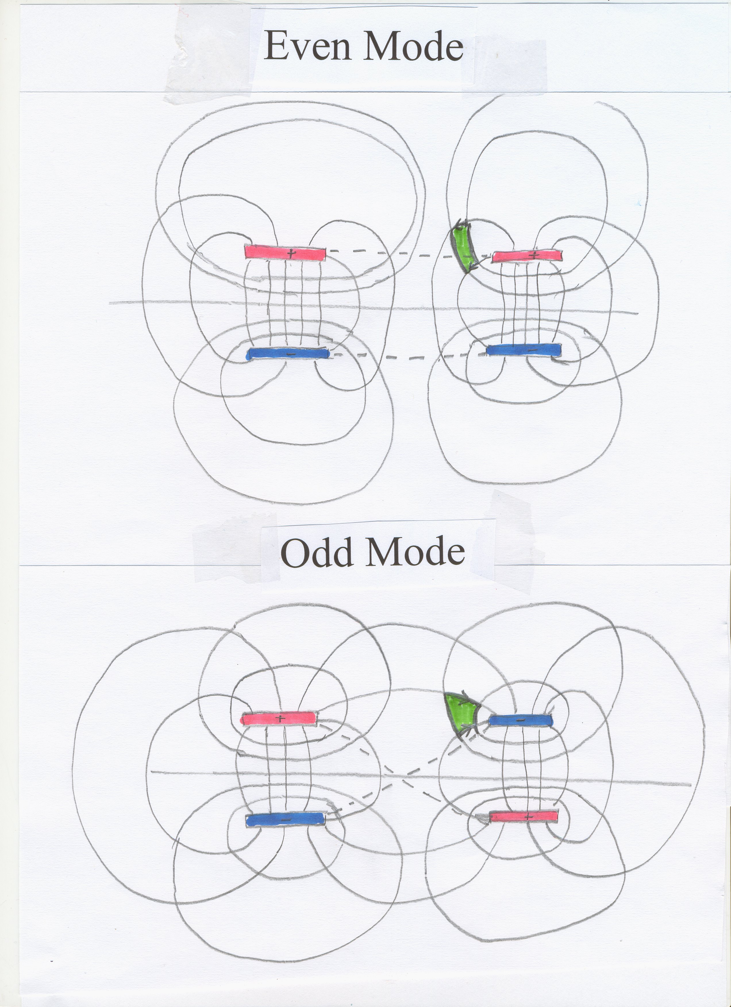
modes, and gave me them incorrectly. However, the key was the idea of two
signal modes, later to be called "Even Mode" and "Odd Mode" .
Using only Faraday’s Law
of Induction and the law of conservation of charge, I developed (and
published) the theory of why a TEM Step travelling down between two
parallel conductors can have only one voltage/current ratio (Zo) and one velocity. It is now at Appendix I , "The
Interconnection of Logic" and "Properties of a Transmission
Line" .
Then using only Faraday’s
Law and the Law of Conservation of Charge, but extending it to mutual
inductance and “mutual capacitance”, I mathematically proved that only two
modes could travel down between a symmetrical double pair of conductors.
This is worked out at Appendix
II and "Crosstalk in digital
systems" .
What I did not prove,
mathematically or otherwise, was that it was physically possible to
superpose the two modes, even and odd. Of course, the photographs I took of
oscilloscope traces 1
, 2 , clearly showed the
two modes superposed, so there seemed to be no problem.
It took me 46 years to
realise that there was indeed
a problem . ( See the smoking gun .) Still,
nobody except myself has noticed. Faraday’s Law does not permit the
superposition of two modes. The mathematics made no distinction between a
case where superposition was permissible and a case, like Faraday’s, where
superposition was not. So why did the use of Faraday’s Law falsely lead me
to a conclusion which the photographs 1 , 2 indicate is valid, if indeed
Faraday’s Law was contradicted? Independently I have shown that Faraday's
Law is faulty. Throughout the Faraday experiment, TEM Waves were
involved, and never was there isolated electric field, electric current or
magnetic field. This is just one example of the way that in a highly
physical, not mathematical, subject like electromagnetic theory, the
mathematics is merely a metaphor for physical reality. At other points the
products of the mathematics break down, for instance as demonstrated by "The Catt
Question" . Of course, this problem disappears if we migrate from
classical theory to Theory C
, which excludes electric current anyway, and so completely bypasses "The Catt
Question". Under Theory
C , electric charge and electric current are the physically
non-existent results of mathematical manipulation of the Energy Current
electromagnetic field. Faraday’s Law is a complex development from the
starting point of the Energy Current TEM Wave, and not the starting point from
which the TEM Wave is developed, in the traditional way. For more than a
century, the cart has been before the horse. Since Faraday's
Law was developed from slowly changing fields, it is dubious, as I have
shown.
This month, March 2010, I
asked my co-author David Walton whether, like me, he had ever realised the
implication of Faraday’s Law excluding the superposition of two fields,
whereas the photographs 1 , about which he
was expert, showed that such a thing existed. (The third traces in the
photographs 1
show a situation which Faraday’s Law makes illegal.) He said that he too
had not realised this. I also asked him the question of why Energy Current,
the central feature of Theory C
, demands symmetry in its environment, "Even Mode" and "Odd Mode" . Both
have a symmetrical appearance to the conductors which are guiding them. He
agreed that it was not clear to us. The answer will be buried in Figure 30 , where Energy Current
continues to the right in a vacuum but also slowly, and minimally,
penetrates north and south into nearly perfect conductors. (It would not
penetrate a perfect conductor at all.) We know that the TEM field will
approach a perfect conductor at right angles. It has to, to remain TEM.
Perhaps this is the constraint which limits the possible modes in a four
wire system to two, "Even
Mode" and "Odd
Mode" . This requires more thought.
In March 2010 David
Walton and I agreed that the illegal (according to Faraday’s Law) situation
was already known to us decades ago when two TEM pulses from opposite
directions travelled through each other in a coaxial cable. However, we
agreed that under classical theory, the case in the diagram of "Even Mode" and "Odd Mode"
travelling in the same space in the same direction but upside down to each
other was more grotesque than in the case of crosstalk.
Questions for Classical Electrodynamics
The four major problems
are;
Displacement Current.
The Catt Question.
Faraday's
Law.
Pictures deriving from
Crosstalk Theory.
1.
Displacement Current.
This paper points out an oversight
which has continued for a century. This is discussed in my article at http://www.ivorcatt.co.uk/41.htm
Displacement Current.
Our article in December
1978 pointed out that electric charge entering the plate of a capacitor
did not immediately desire to traverse the space between the capacitor
plates. (Bleaney
is wrong when (s)he writes that the field between
the plates is uniform.) After entering the capacitor plate from the input
wire, the charge first has to spread itself across the plate. Only then can
it express a desire to traverse the space between the plates.
This desire led to "Maxwell's leap of genius",
Displacement Current. Maxwell himself, and all those who followed him and
worshipped him, failed to notice that after entering the capacitor plate
from the input wire, the charge had first to spread itself across the
plate. This intermediate step has been ignored by all text books and
lecturers. Since we pointed it out in December 1978 , it has been
ignored for a further quarter century. All of today's text books are
written as though this problem, of charge spreading out across the plate,
remains unnoticed, like the Emperor's nakedness.
The spreading out of electric charge across the
capacitor plate is real electric current, and must cause real magnetic
field, according to Ampere's Rule or the Biot-Savart
Law. The alleged genius of Maxwell was that the notional electric current,
called by Maxwell "Displacement Current", was invented to produce
magnetic field and so lead to key conclusions. Since the key (and only)
purpose of Displacement Current
is to cause magnetic field, it is unacceptable that there continues to be
no discussion of the magnetic field which must be caused by the much more
real electric current as the electric charge spreads out across the plate
from the incoming wire.
The archetype for this
kind of myopia is Professor W H
G Lewin.
His lectures,
including that on Displacement
Current, are celebrated worldwide. He has been given prizes for
lecturing excellence. Looking at his lecture, we can
learn a great deal. Early on he draws a uniform electric field in the
capacitor, but later on he says; “There is also a current going up on these
plates .... “. He draws an electric current travelling along the capacitor
plate at right angles to the horizontal current, which means that the
horizontal electric field in the capacitor cannot be uniform. He refuses
to discuss with me the magnetic field generated by this electric current.
(Compare with Walter
still makes time to reply to every single e-mail he gets from his internet
fans .) However, he gets closer than other luminaries to the crisis we
pointed out in December 1978
. No other lecturer or text book writer (including Heaviside)
admits, or notices, that there is such a sideways current flow. Two other
things are notable in his lecture. First is the bemused look on the faces
of the students. Second, we see the arcane mathematics which causes this
bemusement, and convinces the students that they are not capable of
becoming expert in the subject. Of course, his mathematics is not as
Byzantine as that in Wikipedia
and elsewhere.
2.
The Catt Question.
When a TEM Step travels
down a coaxial cable at the speed of light for the dielectric, negative
charge must accumulate on the bottom conductor to terminate the electric
field. That charge cannot reach the required point in time.
3.
Faraday's
Law.
In Faraday’s famous
experiment, a TEM step enters the primary of the transformer. When it has
reached half way across the transformer, the change in magnetic field in
the primary should cause a voltage to be registered to the far right in the
voltmeter, but it measures no voltage because no signal has yet reached it.
4.
Pictures deriving from Crosstalk
Theory.
I have only just realised
that the Pictures
deriving from experiment show that there can be two distinct electric
fields and two distinct magnetic fields, that is, two energy currents, at
one point in space at the same instant of time, which defies Faraday’s Law.
He agre
@@@@@@@@@@@@@@@@@@@
Crosstalk (Noise) in Digital Systems
Pages
1 , 2 , 3 , 4 , 5 , 6 , 7 , 8 , 9 , 10 , 11 , 12 , 13 , 14 , 15 , 16 , 17 , 18 , 19 , 20 , 21 , some of which is in two
of my books. The argument starts at page 30 of one book , and at page 4 of the other book
, continuing on page
55 . Here in
figure 9.2 we see “a very narrow pulse introduced at the front end of the
active line. If there were no parallel passive line nearby, this pulse
would travel down the active line (at the speed of light for the
dielectric) more or less unchanged,” in a TEM mode. “However, as the other
two traces show, the presence of the passive line caused the original
narrow pulse to break up into two similar pulses.”
He agre
@@@@@@@@@@@@@@@@@@@
The Role of the Luminary
How
do "Questions for
Classical Electrodynamics" appear
to accredited luminaries – Professors of Electronics, text book writers,
journal referees and the like? The challenge they face is formidable. They
are deeply immersed in a number of red herrings;
Wave-Particle
dualism is the Kiss of Death to an attempt to grasp the discussion.
Particles have to be removed from our consciousness.
A
major barrier to their grasping the real subject is the wrong theory for a
TEM Wave , "The Rolling Wave"
, which we can be sure all of them adhere to. This makes it extremely hard
for them to grasp the idea that the same amount of energy is travelling
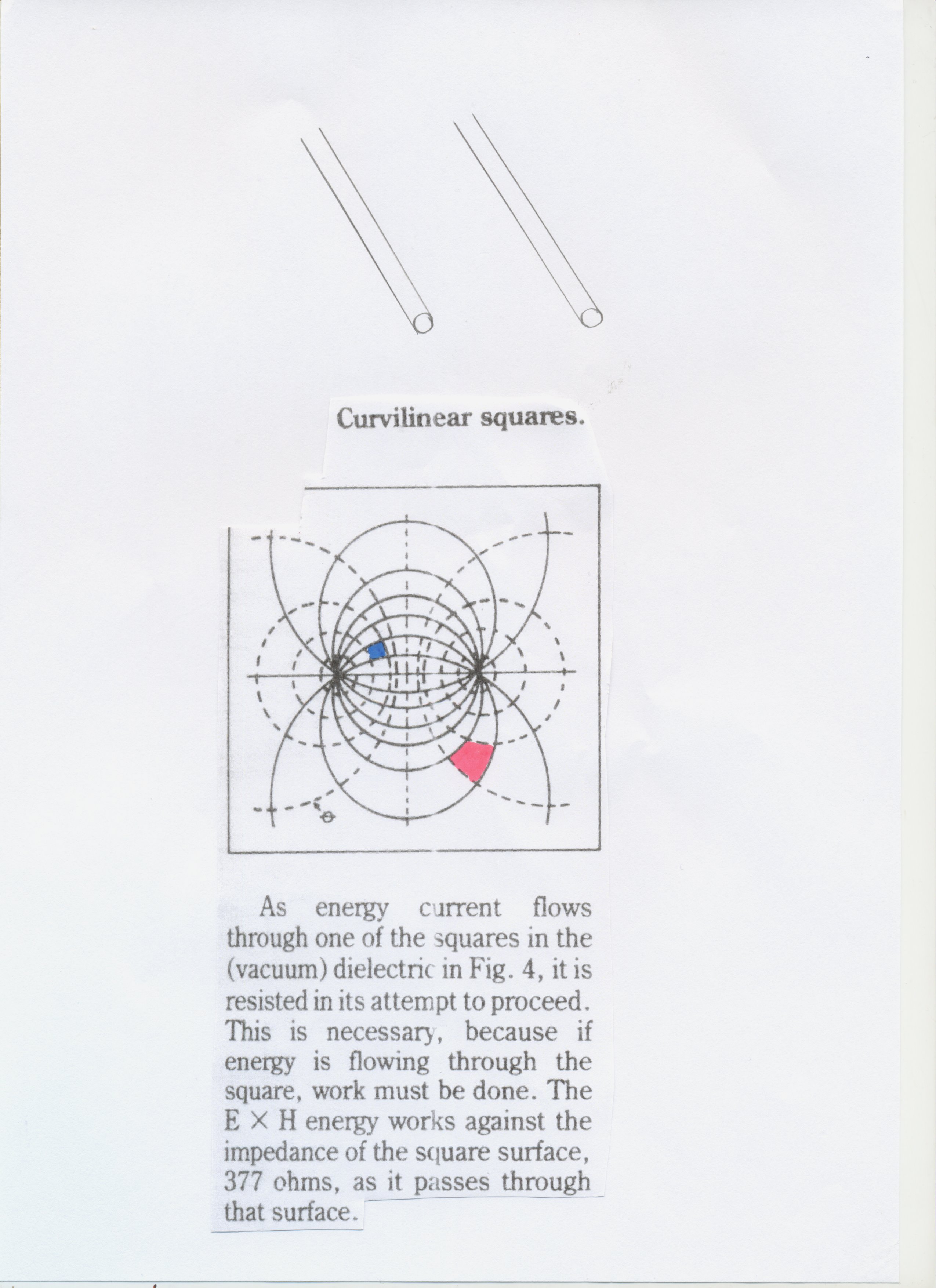
through the red square and the blue square in the diagram. In fact, they
do not even know the diagram. (If they did, they would draw it in their text books. The diagram is very
important, because the
same field pattern occurs with L, C, R and Zo.) I found it in only one
text book fifty years ago, and cannot find it on the www. The only place
where I can find it in what is available today is in Figure 2 of my own book.
However, here we only see one of the two necessary sets of lines to
illustrate the all-important curvilinear
squares . (I find
“curvilinear squares” on Google, but they refer to water flow and paid-for
electronics articles.) They might well know the pattern made by iron filings above a
magnet, but this does not mean that they are familiar with curvilinear squares , and
their association with the Poynting Vector. Wikipedia
does not have the diagram, and neither do other www pages on “The Poynting Vector”. Familiarity with the diagram is necessary. I
have only recently realised that this field pattern is not available to a
professor or text book writer. Lacking that picture, and also thinking that
E causes H causes E "The Rolling
Wave" , it is almost impossible for them to think clearly about the
second, third and fourth Questions above.
No
professor or text book writer has ever considered two pulses from opposite
directions overlapping in a coaxial cable as they pass through each other.
This is a very early case which repudiates Einstein's "The Rolling Wave"
model for the TEM Wave. Another well known case which repudiates it is the
case of white light, multi-frequency, where According to "The Rolling Wave" model for a TEM Wave the positive change of
magnetic field for one colour must be causing one E field at the same time
in the same place as the negatively changing magnetic field in another
colour of light is causing an opposite E field. For a century, there has
been plenty of unnoticed evidence which finally led to the greater
absurdity of comparing Faraday's
Law with the photographs
deriving from crosstalk
experiments , where we clearly have two electric and two magnetic
fields at the same point in space. This evidence does not require migration
from the standard Theory N
to Theory H or Theory C.
The
idea that a TEM Wave must be sinusoidal is pervasive. To confirm this, do a
Google search for “TEM Wave” or “Transverse Electromagnetic Wave”. If a
sine wave is imposed on any of the above four Questions, it submerges the
Question in confusion. Of course, it is difficult to see how a
non-sinusoidal TEM Wave could propagate according to "The Rolling Wave"
theory. That is, "The
Rolling Wave" excludes the
possibility that one logic gate can communicate with the next! It excludes
the most fundamental element in digital electronics. Classical Electrodynamics
, trapped in "The
Rolling Wave" , doggedly ignores digital electronics, which is
more than 95% of electronics today.
|