|
Questions
for Classical Electrodynamics
The
Nature of Space (The first March 2010 advance.)
Ivor Catt. 12th
March 2010.
This realisation took 46
years to come to me. (The 1964 paper, once written, was
blocked for three years. )
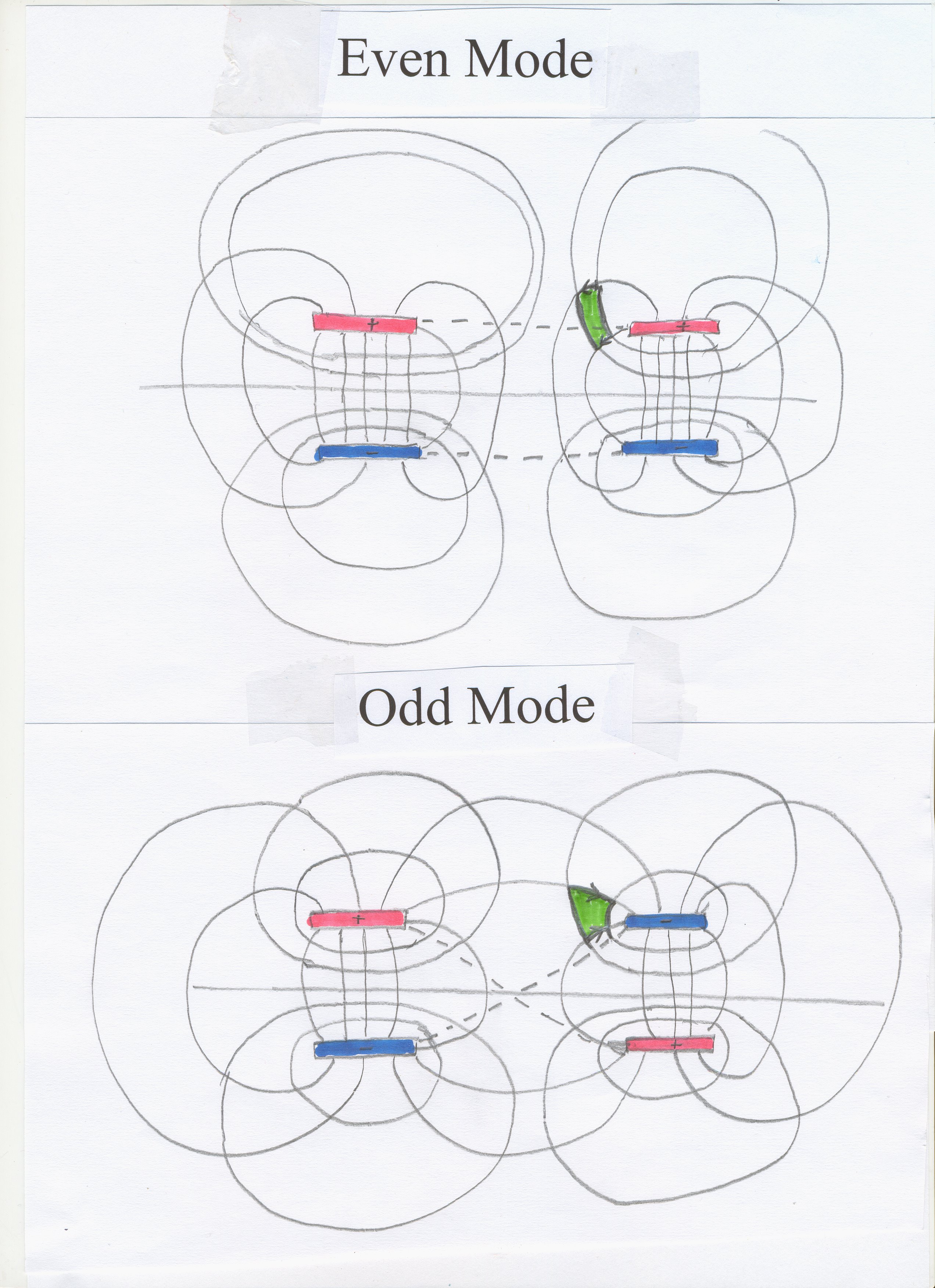
First please realise that the practical
case , of two parallel lines, one active and one passive, above a
ground plane, is equivalent to the case where, using the fact that a copper
plane is a mirror, we use the “method of images”, and replace the two lines
and plane by four lines .
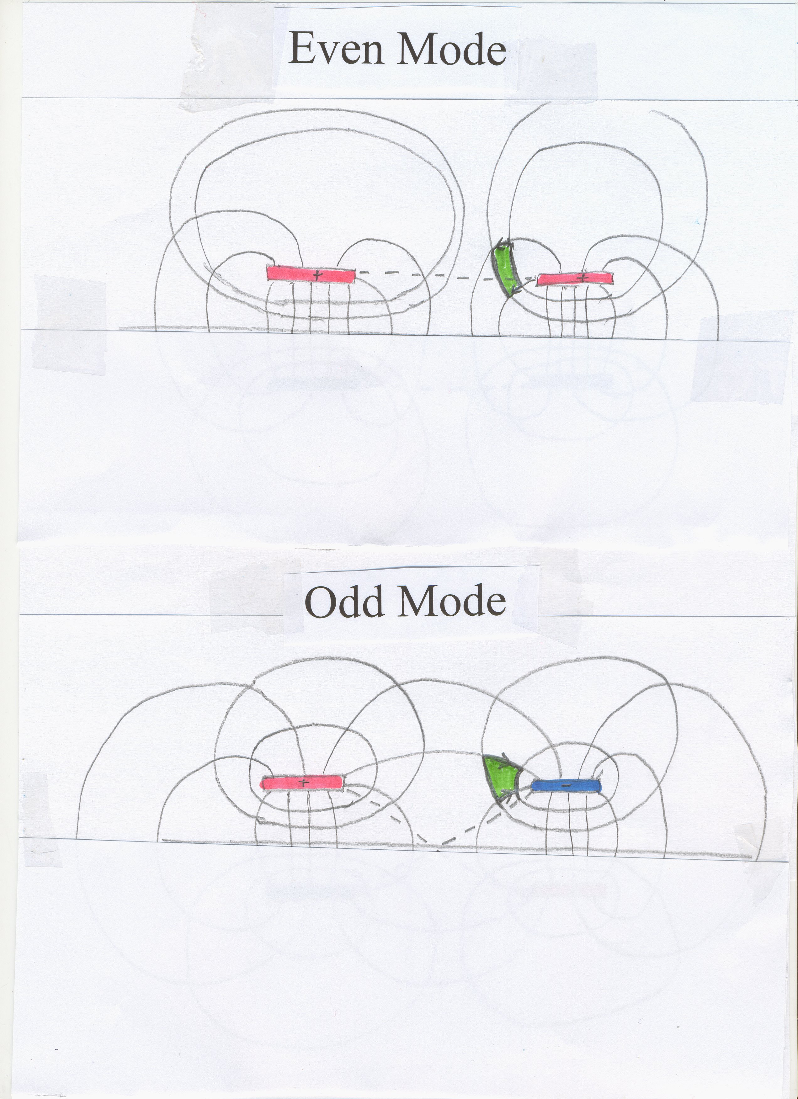
In the paper, it is asserted that it is impossible for a signal to travel
down one pair of wires and leave an adjacent pair of wires unaffected. It
says that two modes can exist; one mode where it is as if the top wires in
each pair are shorted together and the bottom two wires shorted together
(Figure 39 in http://www.ivorcatt.co.uk/4_1.htm
), called "The Even
Mode" . The other possible mode, called "The Odd Mode" ,
is as if pairs of wires are shorted together in a diagonal fashion (Figure
40). The paper then says, in http://www.ivorcatt.co.uk/4_2.htm
;
It
is not possible for a current voltage signal to travel from A1G1
to A2G2 and leave the line P1P2
unaffected. Two fundamental TEM modes can exist on a pair of parallel
conducting strips between parallel ground planes.
Further on,
the possibility of superposition of the two modes is assumed, but not
discussed.
I ask
anyone reading this to print http://www.ivorcatt.org/digihwdesignp57.htm
and refer to it while reading. The two possible modes are mathematically
proven in my paper, http://www.ivorcatt.org/x0330.jpg
and my 1995 book ,
enlarging on the proof for a two wire system at http://www.ivorcatt.org/x0329.jpg
, again in my book . They
are illustrated in at http://www.ivorcatt.org/digihwdesignp57.htm
. However, the whole exercise is based partly on Faraday’s Law of induction.
See http://www.ivorcatt.co.uk/4_1.htm
“Properties of a Transmission Line”
Faraday’s
Law states that changing magnetic flux through a surface causes an emf
around its circumference. Superposition – a positive changing magnetic flux
causing a positive emf and at the same time a negative changing magnetic
flux causing a negative emf – is not permitted. It defies the assumed
physical reality, that one point in space can only have one magnetic flux density.
That is, the superposition of odd
mode and even mode is
not permitted as a result of the application of Faraday’s Law. Note that in
the diagram, the energy entering the paper in the green square for the even mode has the electric
field dropping from positive towards negative from right to left. In the
case of the odd mode ,
the energy entering the paper in the green square has the electric field
dropping from positive to negative from left to right. That is, one energy
current (even mode) is upside down compared with the other energy current
(odd mode) travelling in the same direction. Pace Faraday’s Law, the photographs are
convincing evidence that there really are two different electric fields at
one point in space. However, work on high speed digital electronics led to the
realisation that Faraday’s discovery of electromagnetic induction was
misunderstood by him and by everyone else. Space certainly has physical
properties, 377 and 300,000, and it can accomodate energy. However, the way
it accomodates energy is discovered more deeply during the last two weeks.
Cameo
Now for
the practical case where two Energy Currents, or TEM Waves, of opposite
polarity are travelling at the same point in time and space, both
supposedly (according to Einstein
and Feynman ) partly caused by changing magnetic flux. Look at the
pictures in my book "Digital
Hardware Design" . In Fugure 9.3 the key trace is the third trace.
This is because the other two traces see the single spike breaking up into two
spikes, one positive and one negative. The idea that the two spikes are
superposed in the third trace is compelling. Since they travel at different
velocities, they later separate out, see traces 2 and 1.
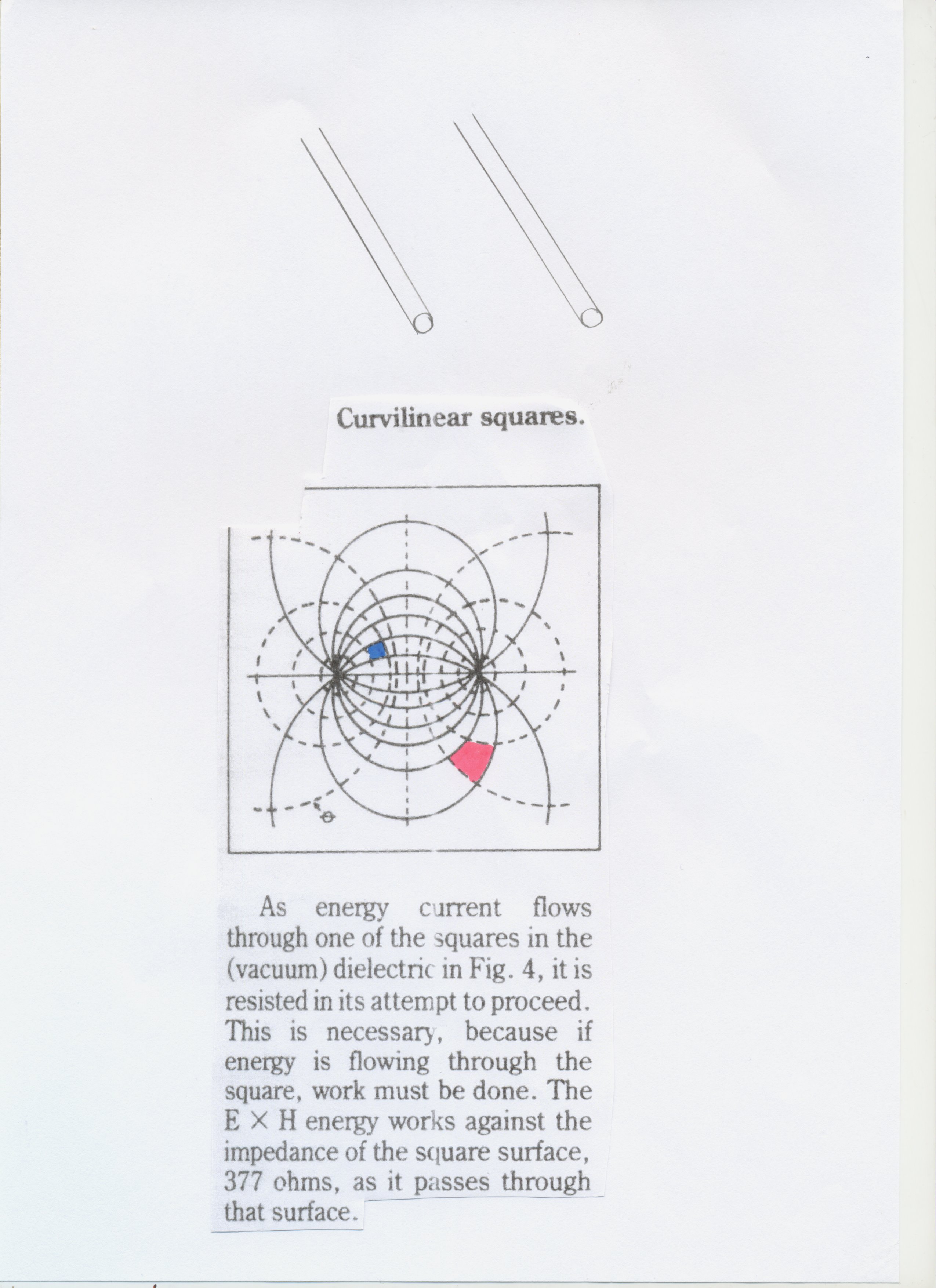
I
presume that we agree that the energy travels as a TEM Wave (or
approximately TEM Wave) through the dielectric guided by the conductors. (As an example, see http://www.ivorcatt.co.uk/x0336.jpg
for a single pair of conductors. The amount of energy flowing through the
red cross section, or square, equals the amount of energy flowing through
the blue cross section.) The greatest energy density is in the space close to the conductors.
Close to the passive line, we see from the third trace that two energy
currents of opposite “polarity” are superposed. One has vertically upwards
voltage, or electric field, and the other has vertically downwards voltage.
Similarly, the magnetic fields associated with each independent spike are
opposite. The total energy involved is not indicated by the spike in the
third trace, but by the sum of the two spikes in the second or first trace.
Now we
have to think about why the mathematics in my paper predicts a result which
defies Faraday’s Law. This is because at the start of the mathematics, the
possibility of superposition was assumed. In http://www.ivorcatt.co.uk/4_1.htm
, it says;
Crosstalk
in digital systems, or;
Proof
that only two types of wave-front pattern can be
propagated down a system of two similar wires and ground plane.
There follows no discussion about superposition, which is assumed in
the rest of the paper, but obviously illegal (as I only now realise, 46
years later). Thus, the third trace of Figure 9.3 (leading to the second
and first races) refutes the whole tradition of classical electromagnetism.
Where did it all go wrong? The answer is, right at the beginning. Faraday
did not discover electromagnetic induction, and changing magnetic field
does not cause electric field. http://www.electromagnetism.demon.co.uk/images/7877.jpg
. Faraday did not introduce electric current into the primary of his
transformer in his famous experiment;
http://en.wikipedia.org/wiki/Faraday's_law_of_induction
; The
induced electromotive force or EMF in any closed
circuit is equal to the time rate of change of the magnetic
flux through the circuit.[1]
Faraday’s Law
breaks down in the case discussed at http://www.electromagnetism.demon.co.uk/images/7877.jpg
Faraday
introduced a TEM Wave, involving both electric and magnetic flux, and what
came out of his transformer and travelled to his galvanometer was also a
TEM Wave involving both electric and magnetic flux. The way in which the energy
current gets into the secondary of a transformer is indicated in Mike
Gibson’s work reached via http://www.ivorcatt.co.uk/4_6.htm
at http://www.ivorcatt.co.uk/2631.htm
and http://www.gibsonridgesoftware.com/physics/two_turn_inductor/tti_derivation.htm
. Here we have the mathematics of how a TEM Wave enters the primary of a
transformer and then gets into the secondary. Throughout, what is involved
is TEM Waves, not electric fields or magnetic fields in isolation.
Earlier above,
I stated; “The two
possible modes are mathematically proven in my paper at http://www.ivorcatt.org/x0330.jpg
.” This raises questions. Was a mathematical approach incapable of
distinguishing between a case where superposition applies, and one where
superposition does not apply? The answer is, “Yes.” Mathematics is like a
shorthand; an inadequate language lacking precision and detail. The second
question is, “What replaces classical theory, growing from Faraday’s Law
and Oersted’s discovery for the next century or two?” The answer to this is
that waiting in the wings is "Theory
C" . Whereas classical theory makes two electric field densities
at one point illegal, Theory C makes no assertion either way. We failed to
notice that, using Einstein and Feynman’s description of a TEM Wave as "The Rolling Wave"
, it is illegal for two pulses to travel from opposite directions down a
coaxial cable and pass through each other leaving each other unaffected,
since during their overlap there is no magnetic field. This predates
today’s realisation that in the case of crosstalk , two different (upside
down) TEM Waves of energy current travelling in the same direction at a
point.
Another
approach is interesting. A paper recently rejected for publication by
Proc.IEEE (as virtually all my writings have been rejected by all journals
for 40 years) discusses the relationship between mathematics and physics in
the context of electromagnetic theory. The subject began with Faraday and
Oersted, and further embroidery and mathematical enhancements gathered
apace from then on. My rejected paper pointed out that the mathematics of
physics, unlike that of chemistry, which has arrows instead of = signs,
ignores causality. I wrote that had we originated with light, which we all
knew about, we could have worked backwards through the same mathematics and
ended up with Faraday’s Law etc. It was a historical accident that we
started with steady and slowly changing fields, and ended up with the TEM
Wave and light – rapidly changing. We could have started with the light and
ended up with the conventional starting point. In that case, the
justification for electric current and electric charge (and Faraday's
Law ), part of the conventional starting point, would not have been
there, and under Occam’s Razor we would not have included it in our arsenal
of theory. Of course, "The
Catt Question" , combined with Figure 30 , obviates the need
for electric charge and electric current (and therefore of Faraday's
Law , which requires electric current). Now, as a result of my at last
realising that two opposite TEM Waves of energy current travelling in the
same direction at the same point in space can exist together, it becomes
absolutely necessary to begin with light, the TEM Wave and the nature of
space, and work back through mathematics and theory to those parts of
conventional theory which remain valid and useful.
In
particular, this realisation of mine means that space is more sophisticated
than we thought. Starting with space accommodating energy current, we can
proceed to discover more and more about the nature of physical reality. As
it is stated at present, Faraday’s Law will not be part of it, because it
involves electric current, which disappears under "Theory C" .
Ivor Catt. 12th March 2010.
14th March.
Yesterday I made the curvilinear diagram http://www.ivorcatt.co.uk/x0336.jpg
, and discussed it. Only
then came the further realisation that, whereas for the two modes, even and
odd, the polarity of the passive conductor is opposite, it does not follow
that close to this conductor the cross sections of the two energy currents
at a point are exactly opposite. The electric and magnetic dimensions of
the ExH energy currents are not at exactly 180 degrees to each other.
Rather, the two TEM Energy Currents are at an oblique angle to each other,
tending towards 180 degrees. This makes the nature of space even more
extraordinary. Ivor Catt. 14th March 2010
Later on
14th March. I have just talked to Dr. David Walton, my
co-author, on the telephone. He agrees that for the historical record, it
is valuable for us to record exactly who thought/realised what when. He
confirms that he also had not realised that the crosstalk pictures http://www.ivorcatt.org/digihwdesignp57.htm
, with which he is familiar (as co-author) contradicted the requirement of
classical electromagnetic theory that one point in space could only have
one value of field (electric or magnetic) at one instant in time. He agreed
that we already knew this, because of the case when two TEM pulses travel
through each other in opposite directions down a coaxial cable. When the
pulses overlap, the two fields at one point in the dielectric are
independent of each other – they coexist. However, the case discussed in
this page, of two energy currents travelling in the same direction with
independent values for E and H, is more extreme. He also agreed that until
I pointed it out to him, he had not realised that the two energy currents
at a point – from even mode and odd mode – were not (in cross section) at
exactly 180 degrees to each other, but were oblique to each other.
(Possibly at some points the angle is exactly 180 degrees.) Two days ago,
both of us fell into the trap of thinking that since the two signals in the
passive conductor were opposite to each other, the energy currents were
exactly opposite to each other, which we now realise they are not. – Ivor
Catt
@@@@@@@@@@@@@@@@@@@
Analysis
Refer to
http://www.ivorcatt.org/digihwdesignp57.htm
Figure
9.3. The bottom trace is what appears on the passive line when a spike
(Figure 9.2) is introduced into the parallel active line. ( See diagram. ) The
voltage amplitude of the bottom spike is an indication of the amount of
energy it contains. However, it breaks up into two spikes, trace 2, which
total more than the original spike. This forces us to accept the obvious,
that the two spikes, trace 2, previously combined to camouflage each other
in the first spike, trace 3. Also note the gradual degradation between
trace 2 and trace 3 (but perhaps near to constant area). This means that
the original two superposed spikes making up the small spike, trace 3, if
treated separately, were very much larger. In fact, since the two spikes in
trace 2 of figure 9.2 derive from the very large spike of trace 3, Figure
9.2, it is obvious that the two superposed spikes given by trace 3 in
Figure 9.3 are large, containing much more energy than the small visible
spike, trace 3 of Figure 9.3, indicates. Thus, consideration of
conservation of energy forces us to conclude that the third trace, Figure
9.3, is two large spikes superposed. Now under classical theory, each
superposed spike contains not only energy but also magnetic and electric
field, of opposite polarities. This is illegal under classical
electromagnetic theory, which derives from Faraday’s Law et al. Classical
theory only permits one electric field density and one magnetic field
density at one point in space and time. Analysis of these pictures forces
us to migrate away from classical theory, perhaps to "Theory C" .
He agre
@@@@@@@@@@@@@@@@@@@
Crosstalk (Noise) in Digital Systems
Pages
1 , 2 , 3 , 4 , 5 , 6 , 7 , 8 , 9 , 10 , 11 , 12 , 13 , 14 , 15 , 16 , 17 , 18 , 19 , 20 , 21 , some of which is in two
of my books. The argument starts at page 30 of one book , and at page 4 of the other book
, continuing on page
55 . Here in
figure 9.2 we see “a very narrow pulse introduced at the front end of the
active line. If there were no parallel passive line nearby, this pulse
would travel down the active line (at the speed of light for the
dielectric) more or less unchanged,” in a TEM mode. “However, as the other
two traces show, the presence of the passive line caused the original
narrow pulse to break up into two similar pulses.”
|