Ivor Catt. 30.4.2040 I had no idea before yesterday
that this https://blogs.ncl.ac.uk/alexyakovlev/2020/01/
existed. Its content keeps demanding that I reply!
http://www.ivorcatt.co.uk/x147.pdf
http://www.ivorcatt.co.uk/x147.htm
http://www.ivorcatt.co.uk/x1471.pdf
http://www.ivorcatt.co.uk/x1472.pdf
http://www.ivorcatt.co.uk/x1473.pdf Correct
version. The 120 ohms is correctly placed with Figure 42, not 40 (as wrongly in
x1472).
http://www.ivorcatt.co.uk/x1475.htm
The fog clears.
I
am greatly impressed by http://www.ivorcatt.co.uk/x147.pdf
, the product of a mere 32 year old, actually written when he was 29. In recent
times, aged 88, I failed to go through the same mathematical hoops. However,
suddenly it all becomes clear to me.
First
to set the scene. Motorola Phoenix made the fastest (ECL)
logic https://en.wikipedia.org/wiki/Emitter-coupled_logic
, competing with other companies’ less noise sensitive, slower TTL https://en.wikipedia.org/wiki/Transistor%E2%80%93transistor_logic . They hired me in
to Phoenix to investigate this noise sensitivity. I decided that I had to face
up to two major issues. First, what was the “voltage” decoupling between two
planes, +5v and 0v, at a point, and second, what was the crosstalk between two
logic signals lying near and parallel to each other. I deal with the first in http://www.ivorcatt.co.uk/x147.pdf
and elsewhere http://www.ivorcatt.co.uk/x2g.pdf
p904.
Here
I address the crosstalk. My boss Emory Garth went to another Motorola
department down the road in Phoenix, and got them to build printed circuit
boards with two adjacent parallel conductors above a voltage plane, and boards
with signals between voltage planes. Extra length was achieved by having them
go round and round in a spiral, as shown in reduced form in http://www.ivorcatt.co.uk/x147.pdf
figure 6, page 74. One board was made sandwitched
between two voltage planes, Figure 5 p746, which I called “buried conductors”
and another board was made with the wires above a voltage plane, which I called
“surface conductors”. Figure 25 p754. The graphs, Figures 24 and 25, showed that if the lines were separated by a difference
equal to the thickness of the epoxy glass, the maximum crosstalk was acceptably
less than 20% of the logic signal. This was the maximum, and did not relate to
the length of the two lines in proximity.
Now
we come to the work of the 29 year old that I was unable to reproduce until
today. At that time, although my education in electricity during my Engineering
course in Cambridge had been botched (partly because my relevant tutor died), I
had no reason to doubt classical (text book) electromagnetic theory. These
doubts, which should have been caused by http://www.ivorcatt.co.uk/x147.pdf
, only surfaced in my mind decades later.
Previously,
I had had made a board with surface conductors of varying separation, including
pairs widely separated. (I slowed down the signals 10x
by burying the board in water). In that latter case, the crosstalk was very
small, still a small pulse twice the travel time down the length of the
parallel section, but a comparatively large spike appeared at the end. Even
this spike was trivially small for crosstalk, but it meant I could not understand
the mechanism. Fortunately the deputy head of R&D, Walt Seelbach,
supported my desire to keep struggling to understand it.
By
then, I had had three jobs after Ferranti with the (now late) Ken Johnson, the
best technical expert in Ferranti, in Manchester, and so should not have
stumbled on Ken Johnson, coming down the corridor. He should have been 5,000
miles away in Manchester, not in Phoenix. I grabbed him and told him about the
little spike. He replied that there were two modes, and he got them wrong. Decades
later I found out that this was well known in distant microwave circles,
probably including Harry Ricker http://www.ivorcatt.co.uk/ricker.htm
, well away from digital expertise. They talk about “Directional couplers”. https://en.wikipedia.org/wiki/Power_dividers_and_directional_couplers
. However, since they dealt only with sine waves, they only knew the two modes,
not the two different velocities in surface conductors, which I proceeded to
discover. It could be said that a sine wave does not have a velocity, since it
is already there (everywhere).
Now
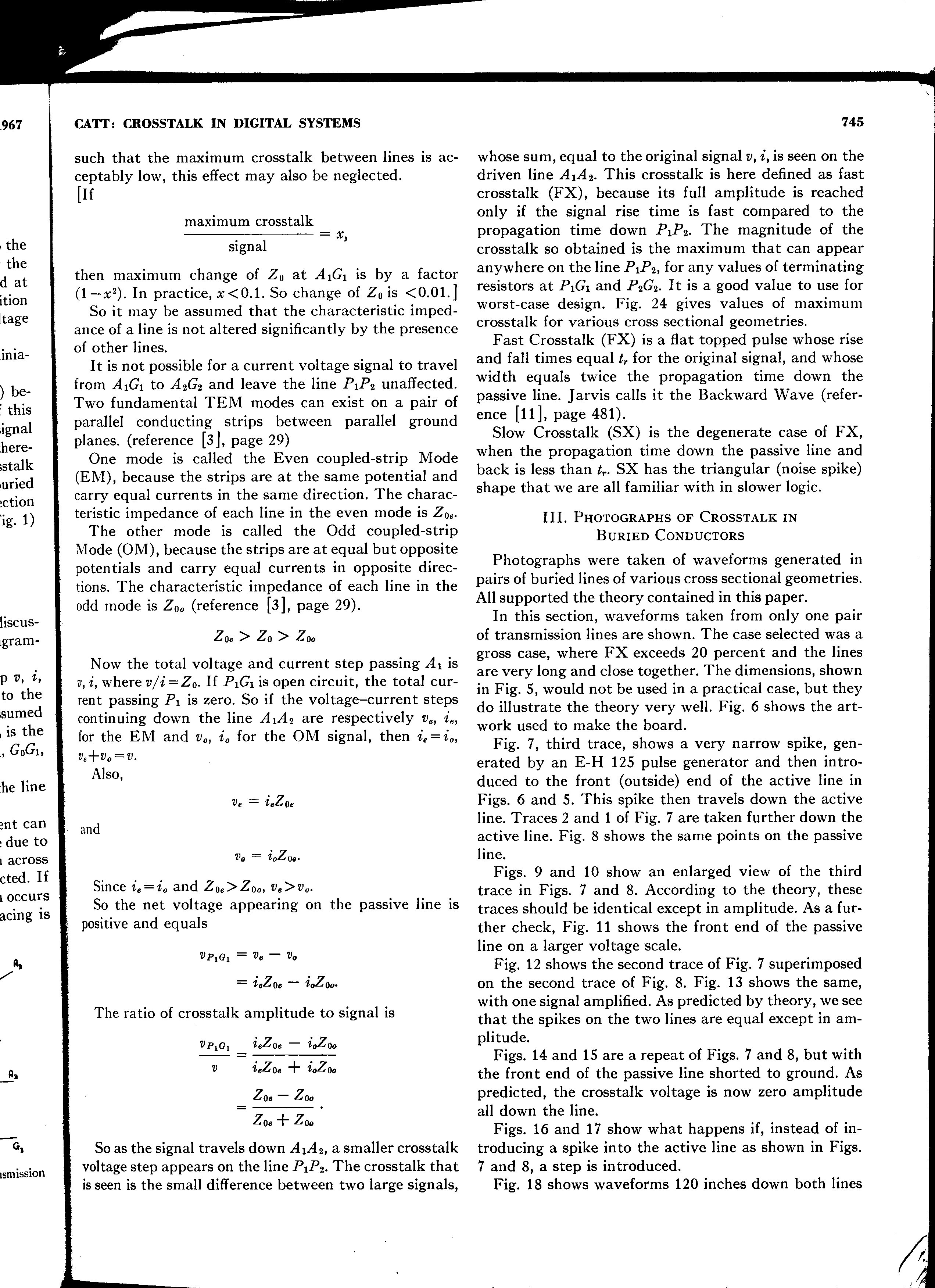
for the work by the 29 year old Catt. We send a narrow spike
down the left hand conductor in Figure 25, p754. This contains electric current
and voltage. The electric current causes magnetic field, and the voltage causes
electric field. See first diagram in http://www.ivorcatt.co.uk/x1471.pdf
. The maths shows that this pattern is illegal. The magnetic field must be
parallel with the surface of a nearby conductor, and the electric field must
end normal (at right angles) to the surface of the conductor, terminating in
electric charge. http://www.ivorcatt.co.uk/x0313.jpg
. The maths shows that only two modes are possible between the two (or four)
conductors, the even mode and the odd mode, where the signals down the wires
are equal, or equal and opposite. (See even and odd
mode diagrams in http://www.ivorcatt.co.uk/x1471.pdf
)
My
maths had a signal travelling at velocity c between the two (or four)
conductors, with equations (1) about the voltage causing an electric field, and
(2) the current causing a magnetic field. Knowing the characteristic impedance
between the wires, I know the relationship between electric and magnetic field,
and can combine the equations, leaving out the velocity. I end up with two
modes, each with a velocity which is different in the case of surface
conductors but the same for buried conductors.
The
lines are about 200 inches long. The top
of this document http://www.ivorcatt.co.uk/x1474.htm
lists the various www locations which take you through the very elegant way
this pair of adjacent lines accommodates signals and their reflection at the
far end when the termination is varied between open circuit, short circuit and
characteristic impedance between the lines.
As
an example, it is possible to terminate one mode so that it does not reflect,
while terminating the other line properly, or shorting it.
These
results, peer reviewed published more than 50 years ago and ignored for good
reason, being the misplacement of the 120 ohms, should now be clear, and be the
cause of a great deal of rumination and discussion during the next decade, but
is more likely to be ignored, silenced. Such is the tragic state of “science”
today.
As
one example of neglect, superposition, ignored today, continually reappears in
these results. Obviously two TEM waves can travel through
each other at a point, more or less ignoring each other. This is only
possible under “Theory d”. http://www.ivorcatt.co.uk/d.htm ,
where E and H coexist, and do not “cause” each other.
Ivor
Catt