|
About classical electrodynamics
The 109
Experiment
This is an attempt to
introduce the layman to the developments of the last three weeks.
We close the switches in Figure 3 and immediately
reopen them. (If we did not reopen them, the result would be as in the animations .) All experts will agree that a very narrow spike
of voltage and current (made up as in Figures 4 and 5 ) advances at the speed of light guided by the two
conductors. Its four constituents are listed here . In the case of my
work, the narrow spike, or pulse, was originally six inches long, lasting
for one tenth of one billionth of a second. It was like a very short flash
of light travelling down between the two conductors. This narrow spike,
which had by now widened to half of one billionth of a second
was introduced between the conductor and the copper plane below in the top
of Figure 23 . Travelling
in the epoxy glass board between the conductors, it narrowed down back to
six inches wide. In the board, it travelled at half the speed of light in a
vacuum or air. It gradually widened further, ending up 270 inches down
between conductor and copper plane to a width of one billionth of a second,
shown in the top trace in Figure
39 (shown upside down).
Next, we introduced the
spike between the left hand conductor and the copper plane, see Figure 9.1 . The
resulting voltages for the active and the passive (right hand) conductor
are shown in traces 3 of Figure 9.2 and Figure 9.3 (and
Figures 28 and 29 ). That is, a smaller voltage spike immediately
appeared on the right hand conductor adjacent to the driven conductor.
This pair of conductors
was very long, and the signals were inspected as they travelled along, 120
inches along (second trace) and 234 inches along (first trace). The initial
spike, large on the line driven and one sixth of the height on the other
line, had broken down into two spikes. The slowest (even mode) one was
equal on each line. The faster (odd mode) one (arriving first) was equal
and opposite. In Figure 33
, the second traces were widened to show this more clearly. Note that in
the first trace
of Figures 9.2 and
9.3 , having travelled twice as far, the two spikes are twice as far
apart. The conclusion is compelling, that in the first trace they are
on top of each other, making a large spike on the active line, Figure 9.2 , and a
small spike on the passive line Figure 9.3 , because
here they are opposite.
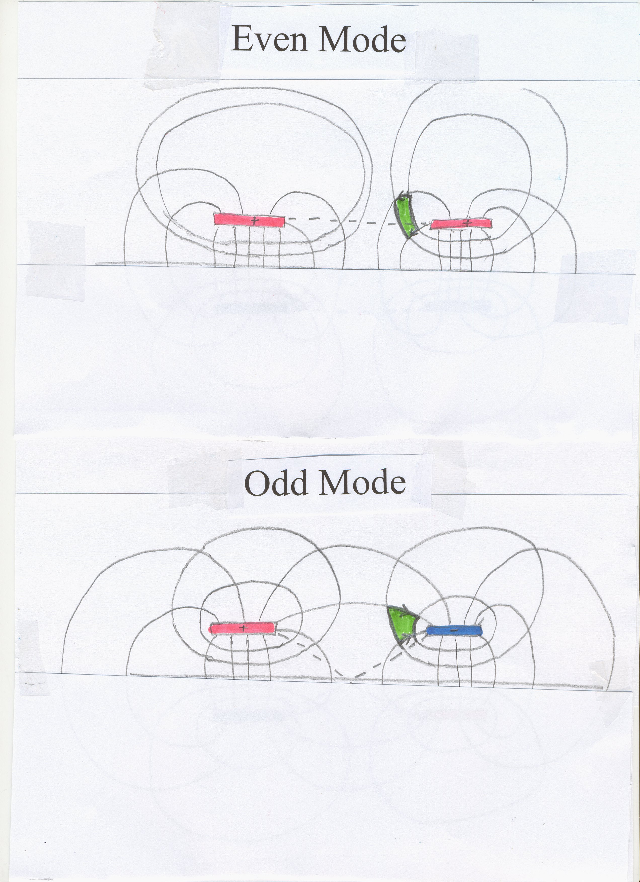
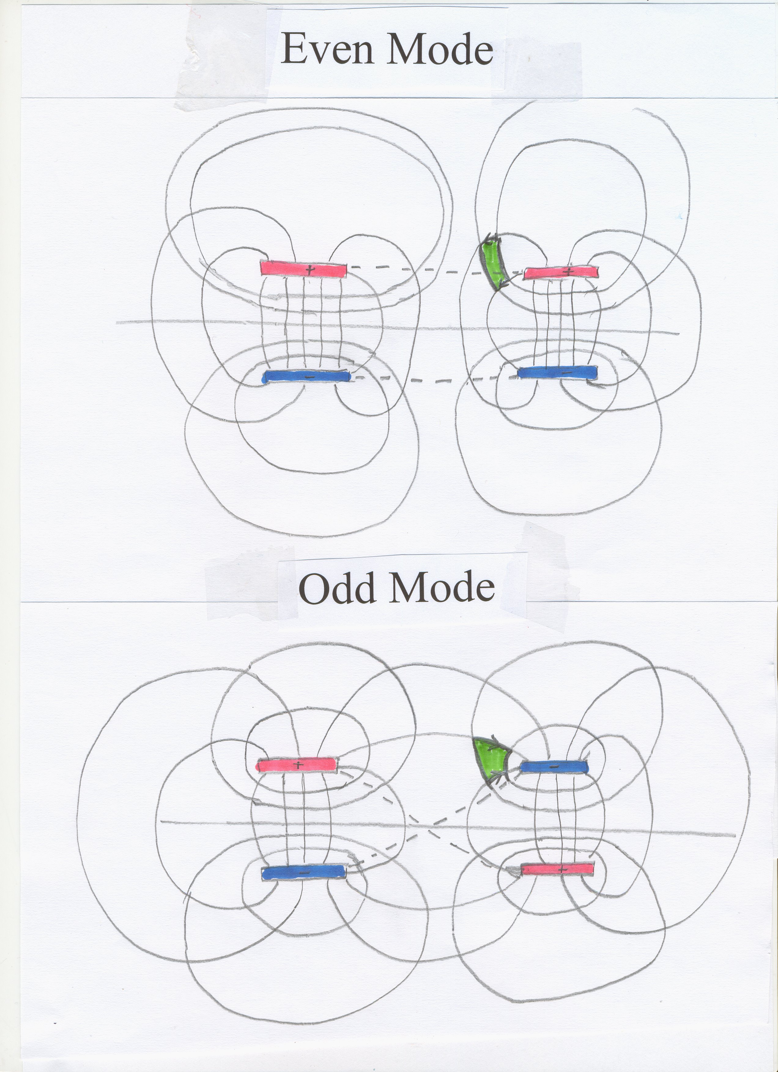
(I have drawn the field patterns for the even mode and odd mode . Since a copper
plane acts as a mirror for light or for electromagnetic waves, it is easier
to think in terms of four
conductors and omit the copper plane.)
Convincing proof that two
TEM Waves of opposite polarity are travelling together near to the passive
line on the right
is provided by Figure
9.5 . Instead of a narrow spike, a step has been introduced into the
active, left hand
line , first trace of Figure 9.4 . This
step is the same as a long series of spikes. In the right hand, passive
line, we see, in the first trace of Figure 9.5 , a step,
which is a series of small spikes. However, in the second and third traces,
the first negative spike separates out by arriving fastest. After that, the
step represents a series of small spikes, positive and negative, superposed,
like the negative and positive spike in the second trace of Figure 9.3 , but
largely cancelling each other out for our voltage measuring instrument.
The idea that two waves
of opposite polarity can travel together in the same region as in the third
trace of Figure 9.3
and the first and second traces of Figure 9.5 contradicts
Faraday's
Law , one of the earliest and most basic laws in the history of
electromagnetic theory. Faraday's
Law , “The induced electromotive force or EMF in any closed
circuit is equal to the time rate of change of the magnetic
flux through the circuit” excludes the possibility of two independent fields at
one point in space, which we see in trace 3 of Figure 9.3 .
“ Faraday's
law is a fundamental relationship which comes from Maxwell's equations. It
serves as a succinct summary of the ways a voltage (or emf)
may be generated by a changing magnetic environment. “
Under Faraday’s Law, there is no possibility of two changing
magnetic environments in the same place, as we see in the third trace of Figure 29 .
@@@@@@@@@@@@@@@@@
Dear
John (Foggitt)
I
have just realised one implication of using the Principle of Superposition
under classical theory.
In
the second and first traces of the photographs in http://www.ivorcatt.org/digihwdesignp57.htm ,
we see first of all a negative spike on the passive line, trace 2 of Figure
9.3 Thus, to terminate the electric field lines as shown in http://www.ivorcatt.co.uk/x0362.jpg or
http://www.ivorcatt.co.uk/x0361.jpg we
need, first, when the odd mode passes by, negative charge density on the
surface of the passive (top
right) line; and then shortly afterwards when the even mode passes by
we need positive charge on the passive (top right) line.
Now
initially, at the third trace of Figure 9.3 , when
the two modes have not yet separated out, you thought there could be two
superposed electric fields. However, we now see that the third trace of Figure 9.3 shows
that initially there has to be on the surface of the passive (top right) line superposed
negative and positive charge. That is, at one point on the surface of the (top right) conductor there
are two charges, one negative and the other positive, until the odd mode
and the even mode separate out. The negative charge terminates the electric
flux field at its negative end, and the positive charge terminates the
electric flux field at its positive end.
Can
two charges of opposite polarity exist at the same point, one terminating
positive electric flux and the other terminating negative electric flux?
This is much more dubious than the idea that two electric fields can exist
at one point, and superposition of their effects (or their causes) applied.
Ivor Catt 14 April 2010
@@@@@@@@@@@@@@@@@
We need a thorough
analysis of the work I did on crosstalk in the 1960s, the mathematics I
developed to prove the limitation to two modes, and the photographs showing
a third, illegal mode.
In my paper "Crosstalk (Noise) in
Digital Systems" I wrote on page 761 , Appendix I;
“Assume that a current
voltage step i, v, is travelling down the [pair
of] parallel lines from left to right .... ” .
Note that I did not say “Assume a single
current voltage step .... ” [Note 1]. I was
trapped in the reigning framework, deriving from Faraday’s Law, which I
proceeded to base the argument and the mathematics on. I concluded that
only one wave-front pattern could travel in such a way at only one
velocity. Then on page 762
I used similar arguments giving “Proof that only two types of wave-front
pattern can be propagated down a system of two wires and a ground plane
[i.e. a symmetrical four wire system].” I (wrongly) began; “Now assume that
a [single] wave front involving current steps ia
and ip is travelling down the lines
with a velocity c.” Note the missing, but implied, word “single”. Here is
the fatal flaw in the whole discussion (leading to the fatal flaw in
Faraday’s Law, which assumes a single field at one point), leading to the “proof” by the pictures .
However, close inspection of the pictures shows
us that although traces 2 and 1 appear to confirm the calculations, and
thus Faraday’s Law, traces 3 disprove it by showing a third (asymmetric)
mode, which is not permitted under "Theory N" , but
acceptable under "Theory
C" .
Of course, an apologist
for Establishment Electromagnetic Theory may want to argue that the small
spike in the bottom trace of Figure 9.3 is not
the combination of two spikes which separate out later in traces 2 and 1.
But only a “scientist” deeply committed to defending theory a century old
would do so. That means, of course, virtually every one of today’s
scientists. However, it is likely that, rather than defending archaic
theory, they will merely ignore the whole of this matter – both the
mathematics and the pictures.
The inadequacy of
mathematics as a language, and the too great faith in it by myself as well
as others, for instance in my 1967 paper , is
discussed by me in my book at 1 and 2 .
Elsewhere I illustrate the multifarious problems by taking x, squaring it,
finding the square root and deducing that the value is now x or –x. Even
within mathematics there are obscurities, even when mathematics is divorced
from physical reality. It is not surprising that I fell into a trap in 1964
when they were combined.
Note 1. I did not have to
say “Assume that a single
current voltage step i, v, is travelling down the
[pair of] parallel lines” because under Faraday’s Law two steps in the same
place at the same time would be illegal. I was then and for decades later a
conscientious follower of Faraday. Now the truth is that if two pulses
travelling in opposite directions down a coaxial cable pass through each
other, there are then two current voltage pulses at the same point for a
time, admittedly not both travelling “from left to right”. Thus, such a
situation already defies Faraday’s Law, and nobody has ever noticed. (Elsewhere
I assert that no professor or text book writer has ever considered {and never
mentioned} two pulses travelling through each other, of course, so they
could not confront this defiance of Faraday’s Law. One can only think about
what one thinks about.)
|