|
About classical electrodynamics
The
109 Experiment
Summary.
In
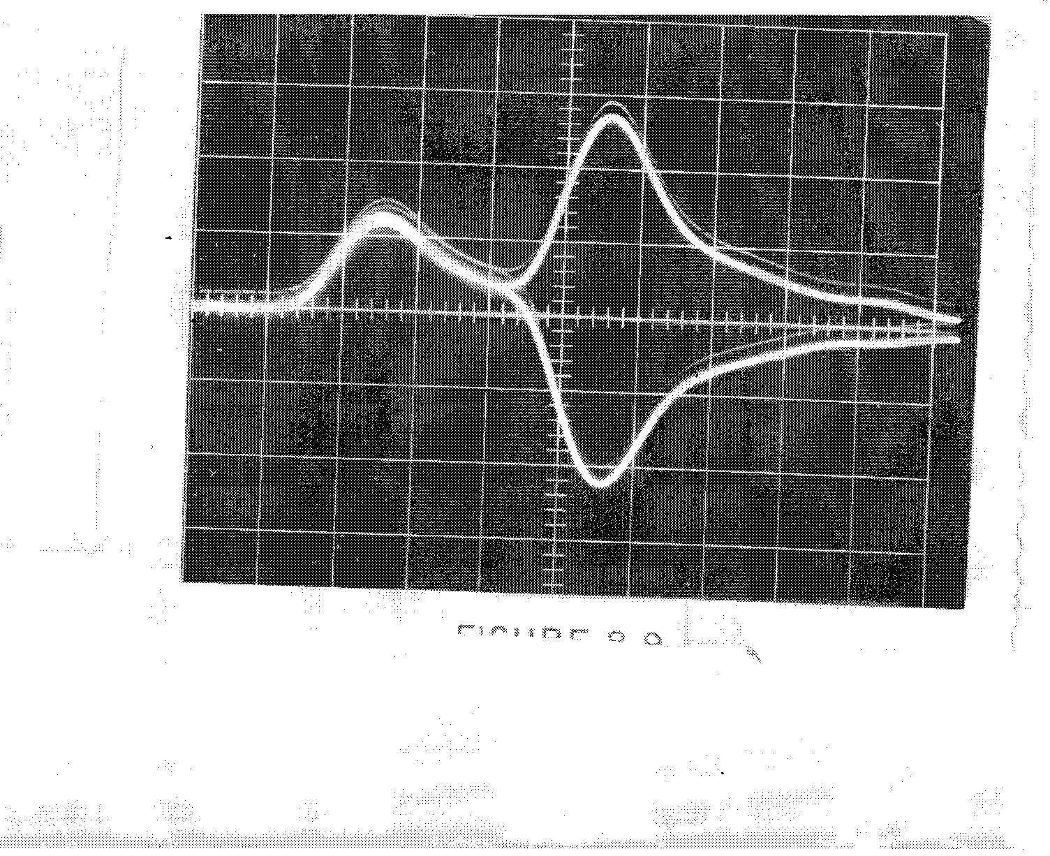
the third traces of Figure
9.2 and Figure 9.3 , we see the effect of inserting a narrow spike
between the left hand
conductor and the voltage plane . Immediately a small spike appears in
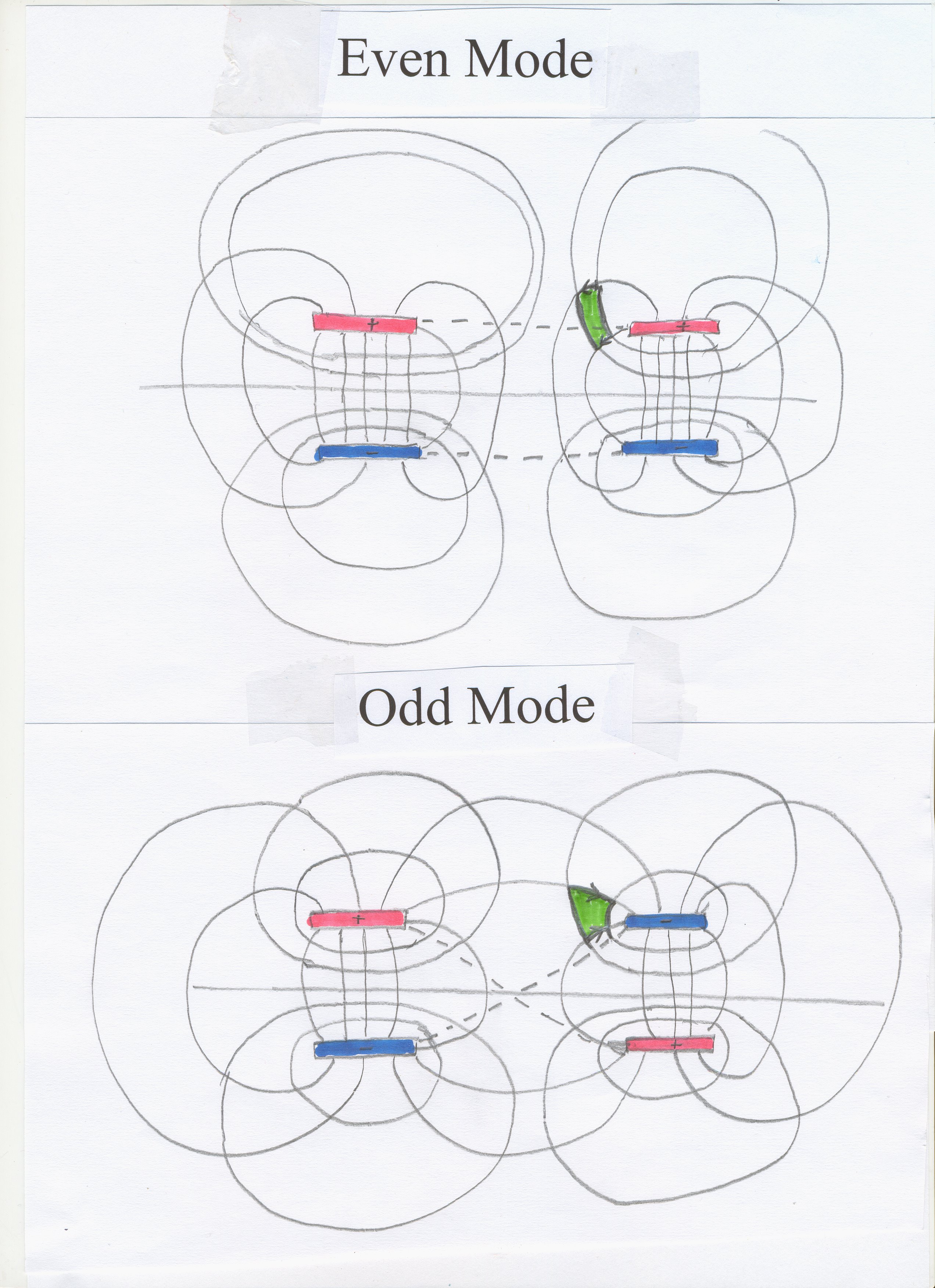
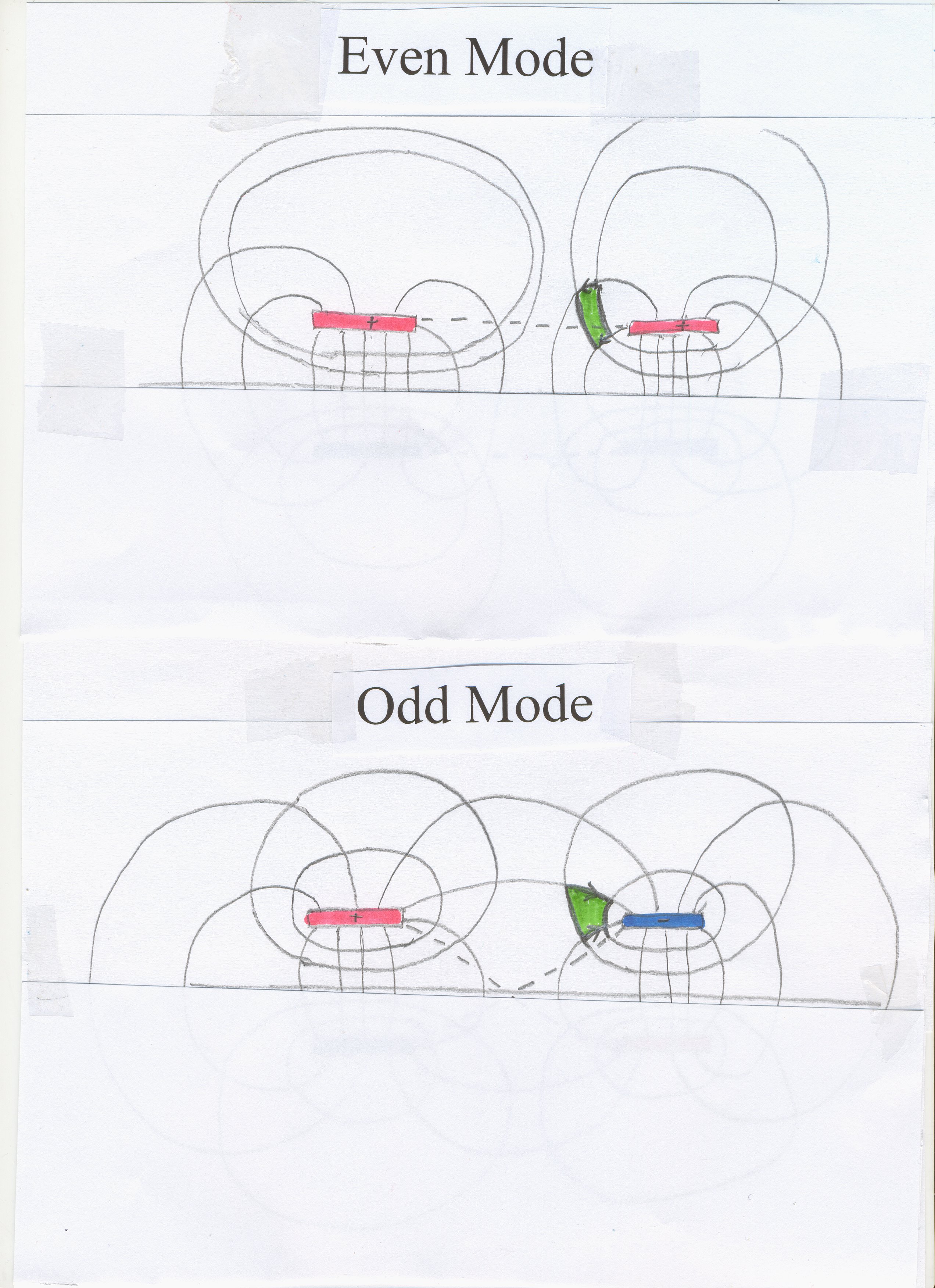
the other, passive line. However, both the spikes break up into two spikes , Odd Mode and Even Mode .
Before they separate out, two TEM Waves, or energy currents , are
superposed. Their energies are both positive, but their electric fields are
in opposite directions. Now since energy is conserved, the idea that the
vector sum of the two electric fields is physically real,
is false. We have two electric fields at the same point at the same instant
in time. They are in approximately opposite directions.
@@@@@@@@@@@@
We deliver a very narrow spike down a coaxial cable into the printed circuit
board between the left hand (active) conductor A and voltage plane. This
spike entering the printed circuit board is shown as the third trace in Figure 9.2 . A
smaller spike appears on the right hand (passive) conductor P, seen as the
third trace in Figure
9.3 . It is easier to move to four conductors, using the method of
images. Every field line hits the conducting copper plate at right angles,
so the situation is essentially the same as in Figure 37 . That is, we move from !
to 2
.
The spike shown in the third trace then
travels at the speed of light (for the printed circuit board), and we see
it 120 inches down the line (second trace) and 234 inches down the line
(first trace) However, we also see that the original single spike has
broken up into two spikes travelling at slightly different velocities.
First comes the Odd Mode spike followed by
the slower Even Mode
spike. Exactly the same spike is seen on the passive line to the right. An enlarged version of traces
2 shows how equal the spikes on the active and passive line are. (This
is even more convincing when the signal on the passive line is inverted .) The later Even Mode spike is as though
the active and passive lines A and P are shorted together as shown in Figure 39 . The earlier Odd Mode spike is as though
the four lines are shorted together as in Figure 40 .
For some reason, probably indicated by Figure 30 , the original spike
needs to travel down between the four conductors in a symmetrical manner.
Had it stayed as in the third traces in Figure 9.2 and Figure
9.3 , it would not have been balanced, or symmetrical. The “proof” that
the original signal has to break up into two signals is given at Figure 37 , building on the
argument at Figure 36 . It
is also at Appendix II ,
building on Appendix I .
However, the third traces of Figure 9.2 and Figure
9.3 defy the mathematical ”proof”, as I failed
to notice for 43 years. Half way between traces 1 and traces 2 we would see
the two spikes partly separated out. The later part of the Odd Mode will
overlap the earlier part of the Even Mode. Looking at the field patterns , we will
have some odd mode energy in the green square with electric field dropping
from left to right superposed on even mode energy travelling in the same
direction with its electric field dropping from right to left. (There
are also two magnetic fields in opposite directions in the green squares.)
Now all energy is positive, so the energies add. However, the
electric fields associated with these two energy densities in the two green
squares are in opposite directions. So taking the vector sum of the
electric fields (i.e. adding them) divorces us from considerations of
energy.
(Another extraordinary fact
is that where the two energy currents overlap, such that there is a superposed
positive voltage and negative voltage on the same passive conductor to the
right, there must be opposite electric currents in the passive line to
create two opposite magnetic fields.)
An electric field contains energy, because when we pull apart the
plates of a charged capacitor, we do work.
Note that it has never been stated that at one point in space there
is only one electric field, but it has always been implied. Generally, the
errors in a theoretical framework are on page 2, not page 527. Usually the
error is not stated, but implied. (A good example is the appearance of
Omega on page 2 of discussion of a TEM Wave. It is not stated whether a TEM
wave must be sinusoidal.)
Now let us discuss the purpose of an electric field. If we hold
onto the idea that one point in space contains only one electric field’s
direction and gradient, then we have to accept that the purposes of
electric fields do not include any consideration of energy. But my position
is that energy is the primary consideration in our science. Walking away
from energy, we walk away from science. This is particularly true in our
case, since the electric field in a charged capacitor contains energy, and
the energy is contained in the electric field, not in the electric charges.
When we move two capacitor plates apart we do work, and the amount of work
relates to the change in electric field. The charges do not change.
Why was it possible to "prove"
“that only two types of wave-front patterns can be propagated down a system
of two wires and ground plane”? In 1967 I conformed to classical
electromagnetic theory. The answer is that following classical theory, it
was assumed by me that electric current existed, so that I started with
Faraday’s Law, which starts with electric current. I also began with the
Law of Conservation of Charge. Under my "Theory C" , electric
current and charge do not exist, so the mathematical procedure leading to a
conclusion discredited by traces 3 in Figure 9.2 and Figure
9.3 would not have begun. As mentioned before in another example, the
error in a scientific process will usually be right at the beginning. I
assumed conservation of charge and Faraday’s Law, which in any case is
discredited elsewhere
.
Under "Theory
C" , electric current and charge are merely the non-existent
mathematical manipulations of very real electric and magnetic fields (or
more properly electromagnetic fields). As in the case of "The Catt
Question" , such figments run into trouble in certain situations,
like the one we see here. Theory C has Energy Current, the TEM Wave,
travelling down guided by the two, or four, conductors. Under "Theory C" , the fact that the incident spike
must break up into two symmetrical spikes has not been proven.
A caveat is that although Figure 9.2 and Figure 9.3
show that the signals are TEM, a waveform travelling in this way in two
different dielectrics, epoxy glass and air, cannot be exactly TEM.
|